How can a fuel cell coating process retain controlled, low-velocity ultrasonic atomization while expanding spray width and production capacity?
The customer challenge
Fuel cell catalyst layers are functional coatings, not decorative films. Their value depends on how consistently catalyst and ionomer are distributed over the active area. When a process is scaled from one nozzle to a larger substrate, simply increasing liquid flow or traverse speed can create new problems: uneven wet loading, visible spray lanes, unstable overlap zones, longer drying times and higher material loss.
The industrial system therefore had to address four linked requirements:
- Scale coating width and throughput without abandoning the controllability of ultrasonic atomization.
- Coordinate eight spray plumes so that overlap regions do not become heavy or light coating bands.
- Maintain repeatable motion, nozzle height and process timing from pass to pass.
- Provide an enclosed, operator-controlled platform suitable for process development and production integration.
Why ultrasonic spray coating?
At each nozzle, ultrasonic vibration forms capillary waves in a thin liquid film and breaks the liquid into a fine, low-velocity spray. Shaping air then guides and widens the plume toward the substrate. For fuel cell catalyst inks, this approach can support controlled liquid delivery, fine atomization and multi-pass deposition while reducing the dependence on very small pressure-nozzle orifices.
The process still requires disciplined ink and recipe control. Catalyst agglomeration, sedimentation, viscosity, solids content, solvent volatility, substrate wetting and inter-pass drying can all influence coating quality. Ultrasonic atomization improves the deposition tool; it does not remove the need to validate the complete ink-to-electrode process.
The engineered solution
| SYSTEM ELEMENT | PROCESS ROLE |
|---|---|
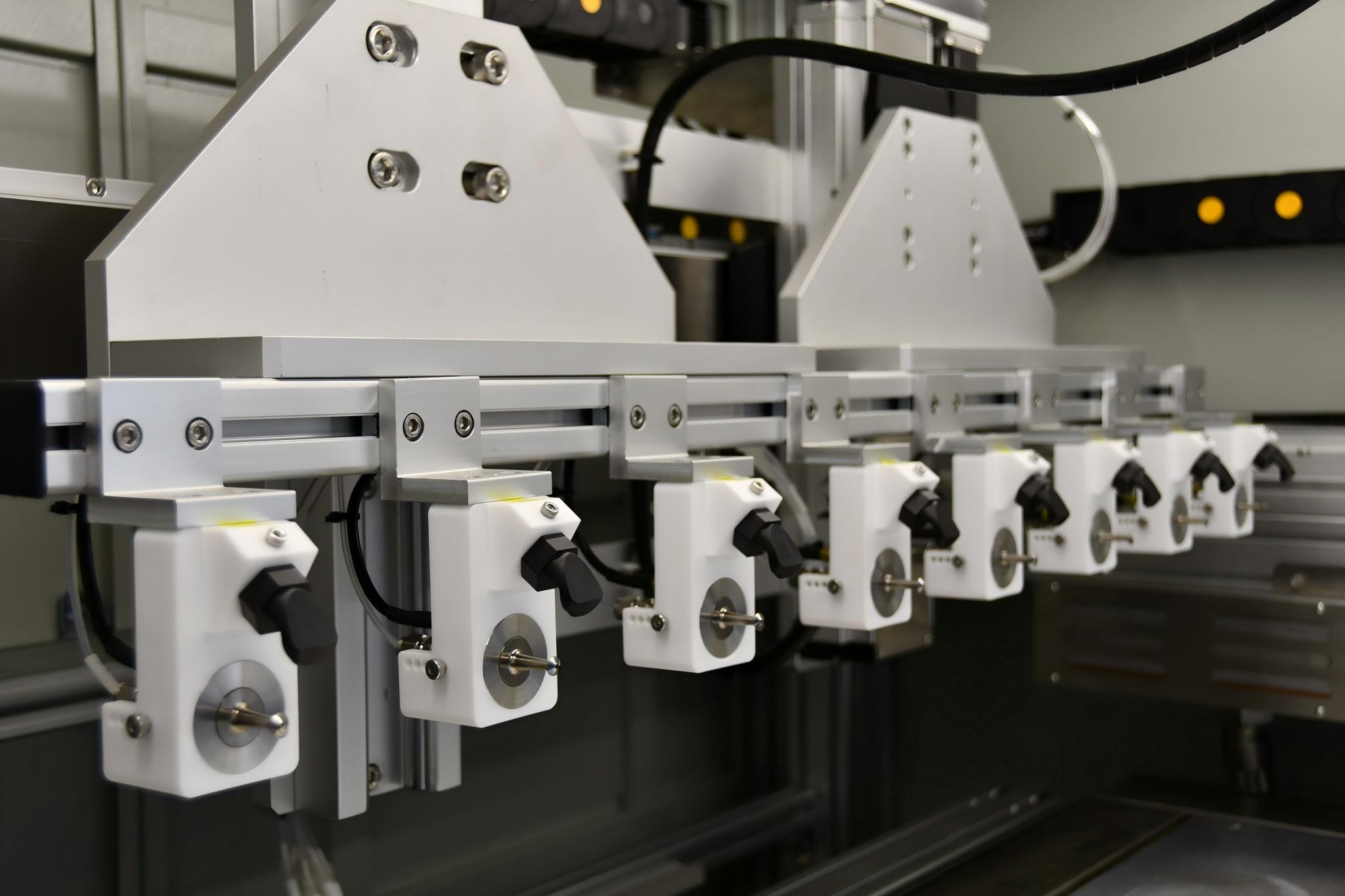
| Eight 60 kHz wide-spray ultrasonic nozzles | Parallel atomization expands the available coating width and distributes the required liquid delivery across multiple spray sources. |
| Adjustable nozzle array | Individual mounting positions support alignment, pitch adjustment and overlap-zone tuning before the production recipe is locked. |
| Automated motion platform | Programmed traverse paths provide controlled scan speed, stroke, pitch and pass count over the working area. |
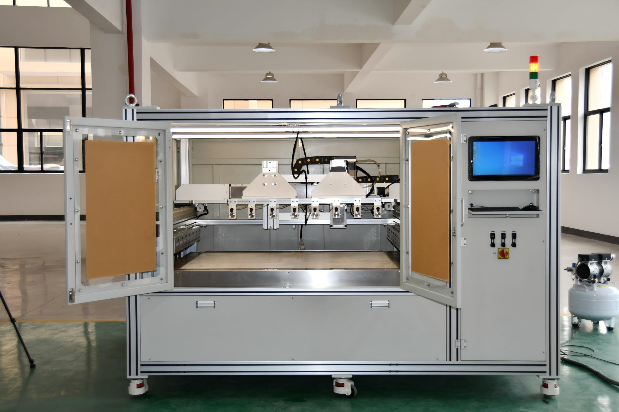
| Enclosed coating chamber | The guarded enclosure separates the moving spray process from the operator and provides a defined space for process control and exhaust integration. |
| Touchscreen and industrial controls | Recipe-oriented control supports repeatable operating sequences, parameter setting and production integration. |
| Temperature-managed work zone | Substrate and drying conditions can be coordinated with spray passes, subject to the validated catalyst-ink recipe. |
How the coating process is established
- Ink qualification Confirm catalyst and ionomer system, solvent blend, solids content, viscosity, particle/agglomerate size, stability and filtration strategy.
- Nozzle balancing Verify liquid delivery and atomization at each nozzle before defining the combined spray field.
- Array geometry Set nozzle pitch, spray height and shaping-air conditions to create controlled overlap between adjacent plumes.
- Motion recipe Develop scan speed, path, edge compensation, pass count and direction strategy for the target active area.
- Wetting and drying Coordinate substrate condition, temperature and inter-pass timing so that each layer deposits without flooding, cracking or excessive edge build-up.
- Validation Measure loading, thickness and uniformity, then confirm electrochemical performance using the customer’s approved fuel cell test method.
Project outcome
The completed platform converts a single-nozzle coating principle into an eight-nozzle industrial architecture. It provides a wider, configurable spray array, automated scanning, enclosed operation and centralized control in one machine. The system creates a practical production platform on which the customer can establish and lock a fuel cell catalyst-coating recipe.
Because final electrode performance depends on the customer’s catalyst ink, substrate, loading target and drying strategy, coating thickness, loading uniformity, material utilization and cell-performance values should only be published after the corresponding inspection and electrochemical test records are approved.
Recommended applications
- Fuel cell catalyst-layer coating on membranes or gas-diffusion substrates, after material compatibility and process validation.
- Large-area or multi-part coating where one nozzle creates an avoidable throughput bottleneck.
- Pilot and production programs that require recipe-controlled, multi-pass deposition and automation integration.
Parameters required for a new project
To configure a similar system, FUNSONIC evaluates the ink formulation and solvent, solids content, viscosity, particle/agglomerate size, substrate type and dimensions, target loading or dry-film thickness, uniformity tolerance, production rate, scan strategy, drying requirements, exhaust and safety conditions, and the required level of automation.
Talk to an application engineer
Share your catalyst ink, substrate size, target loading and required output. FUNSONIC can help define the appropriate nozzle count, spray layout, motion platform and process-validation plan for your fuel cell coating application.